Zenit-Australia Launch Vehicle
Zenit-Australia is a two-stage launch vehicle. It is a development of the Zenit-3SLB launch vehicle, which operated from the Baikonur launch site as a Land Launch project. Zenit-Australia has been developed by Ukrainian rocket provider Yuzhmash, under contract with the Cosmovision Global Corporation. It uses only environmentally-friendly fuels and is capable of injecting payloads of 4000kg to Geotransitional orbit, 8350kg to 500km Sun Synchronous orbit, and 14 000kg to the reference 200km Low Earth Orbit. Zenit-Australia is a further development of the world's most advanced launch vehicles, including the highly successful Zenit-2, Zenit-3SL, and Zenit-3SLB, with the benefit of new experience acquired while developing and manufacturing the 1st stage of USA Antares launch vehicle. Zenit-Australia uses a new propulsion systems for both stages and is completely free of components from Russia or China, employing American or Australian sourced equivalents in their stead.
|
|
Launch Vehicle Specifications:
- Uses liquid oxygen - kerosene fuel for all stages;
- Useful length of the payload compartment is not less than 7530mm;
- Employs automatic flight termination and radio flight termination using 2 UHF receivers at 400-450 MHz on the orbital trajectory until the launch vehicle leaves the Earth's atmosphere.
Payload Compartment Parameters and Operating Environment:
- Inner diameter of the fairing is not less than 4600mm;
- Useful length of the payload compartment is not less than 7530 mm;
- On launch, longitudinal G-forces do not exceed 6G at any time during flight;
- Lateral acceleration of the payload does not exceed 2.35G;
- Acoustic load on the payload is under 135.2 dB;
- Vibration acceleration of the payload does not exceed 40m/s2;
- Payload shock loads are under 1200G;
- Temperature inside the fairing does not exceed 930C.
The components and sub-systems of the 1st and 2nd stages (including propulsion) are modified components of the Zenit, and of the 1st stage of Antares launch vehicles. The guidance and control system (GCS) for Zenit-Australia has been developed and a sample set has been manufactured.
All components of Zenit-Australia are manufactured in Ukraine, USA, EU, and Australia.
Future Satellite Platform
Satellite platform will be developed by Yuzhmash for launches using Zenit-Australia.
The satellite platform will be developed by Yuzhmash for launches using Zenit-Australia.
It will be available in two versions: one using liquid propellants, another using electromagnetic propulsion.
Electromagnetic propulsion engines developed in Ukraine are now manufactured for export.
Platform parameters are in line with other electromagnetic platforms available on the market.
 Zenit-3SLB prior to launch from site 45 at the Baikonur launch site.
|
Zenit-Australia Launch Site
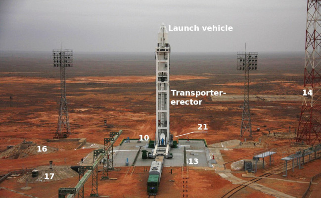
The planned launch site of Zenit-Australia includes the Technical Complex and the Launch Pad. The Technical Complex is the dedicated site for assembly of the launch vehicle and payload integration. Following completion of these operations, the ready to launch, but not fueled, launch vehicle is mounted on transporter-erector and taken to the launch pad. At the Launch Pad, the launch vehicle is fueled, undergoes tests, and lifts off. All Launch Pad operations are fully automated. There are no specific proximity requirements for either the Technical Complex or the Launch pad, as long as transportation to the launch pad meets the dynamic load and air conditioning requirements of the launch vehicle and payload.
Cosmovision Global has completed the preliminary design of the launch site, as seen below:

Here: 1-Vehicle Assembly Building; 2 - Transporter-Erector Inspection Area; 3 - General purpose storage;
4 - Pump Station and Cooling Tower at Vehicle Assembly Site; 5 - Checkpoints; 6 - Tow truck parking; 7 - LOX plant and storage;
8 - Administrative building at Launch Complex; 9 - Power Plant; 10 - Launch Pad; 11 - Fuel Farm; 12 - Thermal Stabilization Station
at Launch Complex; 13 - Fire Fighting Station; 14 - Lightning rod towers; 15 - Escape Gallery at Launch Complex; 16 - Launch Commander
bunker; 17 - Targeting system; 18 - Bottle facility; 19 - Fuel waste facility; 20 - Compressor facility at Launch Complex;
21 - Oxidizer drain facility; 22 - Flame Duct; 23 - Locomotive depot; 24 - Mission Control and Instrumentation site;
25 - Payload preparation facility; 26 - Pump station and cooling tower at Vehicle Assembly site; 27 - Support facility;
28 - Physics and chemistry laboratory; 29 - Climate and Air Control for Vehicle Assembly and Payload Preparation;
30 - Compressor facility for Vehicle Assembly and Payload Preparation.
M2C SCADA and Control Systems Technology
Launch Site Management System (LSMS) is developed using the M2C is developed using the proprietary M2C software architecture technology and the VisCMSE software development suite. The system handles the following tasks:
- Monitoring of facilities and system conditions (e.g. operational, needs maintenance, dysfunctional, etc.);
- Keeping track record of maintenance operations;
- Keeping record of facility and launch site access;
- Automatic reporting of malfunctions and accidents;
- Automatic notification 3rd parties about accidents;
- Automatic generation of daily operational reports;
- Automatic archival of the operations data.
LSMS is developed by COSMOVISION for the Linux environment and is written in the Java-2 language. The system has wireless access to all LS buildings for downloading sensor readings. LSMS will have no internet access and will not be using any office software. Under normal operational conditions, it will generate a daily report in text format, automatically archive it on an optical read-only carrier, and push the copy to the Launch Site Documentation System (LSDC) through a dedicated fibre optics link. In the case of an accident, notifications are pushed in the same way. The general structure of LSMS is presented in the following figure:
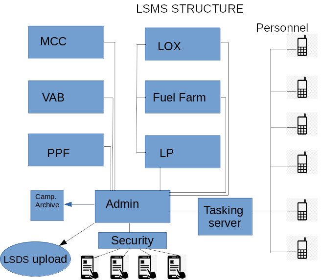 Launch Site Moniroring System architecture
Each server runs a separate M2C application that exports the system state parameters. The application supports control of all available resources and LAN connections for all components of the system (control workstation, operator workstations, data storage and printer-scanner, sensors in the LS buildings, support equipment, handheld devices). It pushes scheduled tasks to handheld devices of LS personnel, pulls reports from LS personnel devices, and presents the system operator with a colour-coded GUI that reflects the current conditions of all system components superimposed on the facility floor plan (see next figure). LSMS supports up to 10 000 data points, with an update rate of once per minute and video feeds from CCTV cameras available on demand.
Alpha-testing of the system for the Spaceport included two buildings (Payload Preparation Facility and Vehicle Assembly Building) with several monitored objects each. The system was tested using a calibrated data stream produced by generators of random numbers. Alpha-testing of the system was completed on August 18, 2023.
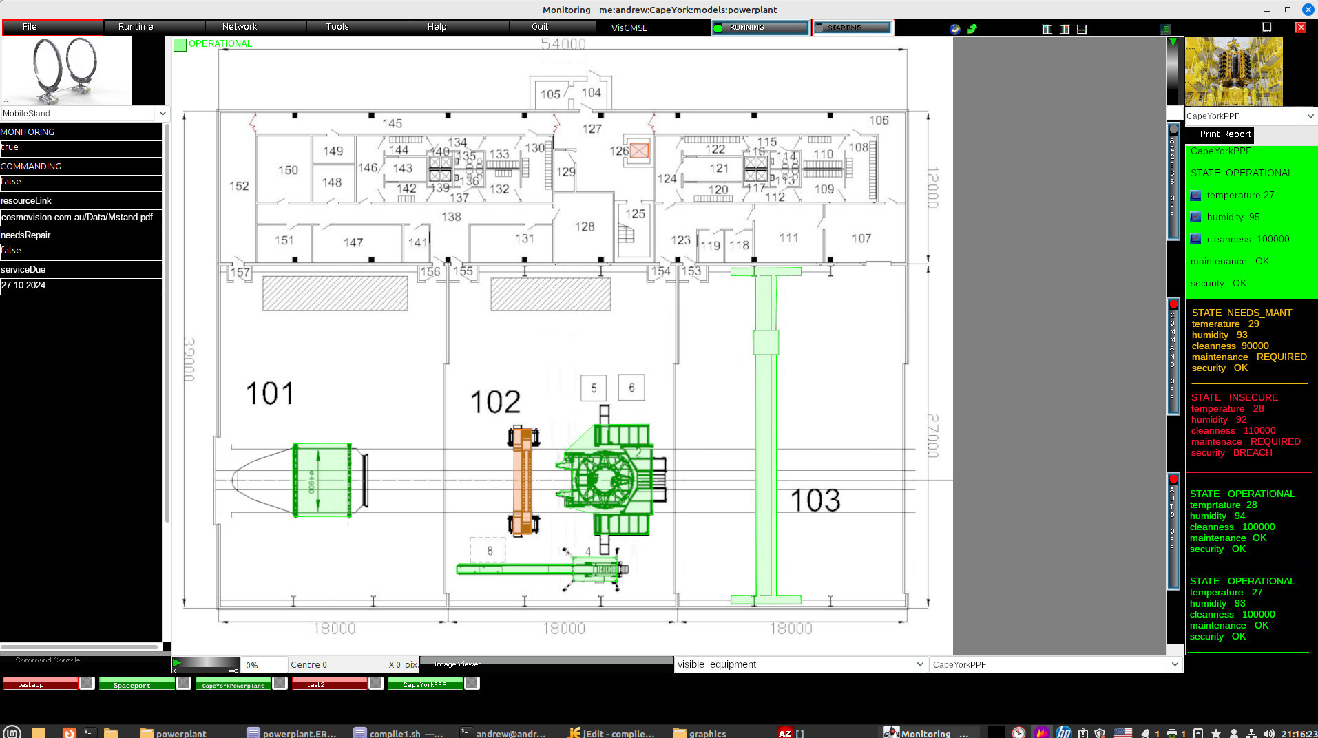 Screenshot of the monitoring system for Payload Preparation Facility (ground level). The monitored system includes a crane, elevator, payload assembly stationary stand, and three pieces of support equipment. In the figure above, one mobile stand and the elevator need repair and thus have different colour coding.
|

